Today, we are here to demystify the construction drawing set! What are construction drawing sets? They are a compilation of drawings that allow general contractors and workers to understand and construct any project. I was never taught how to produce a drawing set, but I’ve heard some schools do! Sooner or later, you will find yourself producing or developing drawings for all projects in the industry, so it’s better to learn now!
It’s common for firms to have specific drawings standards (i.e., standard font, title block, note callout style, etc.) but still have to follow the construction drawings’ standards. Keep in mind this may vary from country or continent, and we can only write from our experiences and knowledge here in North America. We would love to hear about your region’s standards in the comments below! Standards can even vary from client to client (ex. government entities, school boards, etc.).
We are using images from Sater Design to depict some features in the sheets!
Cover Sheet
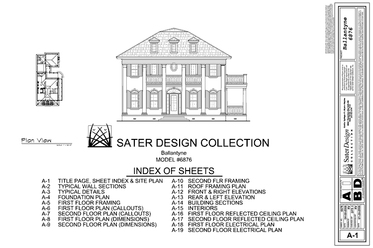
The cover sheet is, you guessed it, the front cover of your construction drawing set. Several key pieces of information belong on the cover sheet, giving any reader the basic information of a project.
- Basic info: name of the project, project number, address of the project, name of client, name of firm are the common information included
- Scope of Work: the building or site plan with the project area outlined (typically dashed or bold line)
- Sheet Index: the table of contents for all the drawings in the set
- Any relevant images, such as the front entrance of the building
- Key Plan: a contextual map showing where your site is located
Cover sheets allow some flexibility for its design depending on the firm’s or client’s standards.
General Notes + Specifications
This sheet is filled with notes from the architect outlining the contractor’s work parameters and is not specific to any drawing. Notes can pertain to site work, floor construction, wall construction, protection of work outside the project area, procedure if unknown and unfavorable conditions are found on-site, and any typical disclaimer that protects the designer in case of a mishap. A typical legend can also be included on this sheet, including hatches for materials, section and elevation markers, etc.
Having a general notes and specifications sheet saves a lot of room on all other sheets, eliminating the need to repeat these notes on every drawing.
Plans Existing (Existing + Proposed)
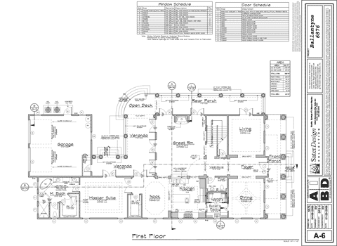
Existing plans show the current conditions on-site before the start of construction. If you’re working on a project with an existing building on-site, it’s important to differentiate between existing and proposed plans in the drawing set. Otherwise, you can continue working on the proposed plans. Existing plans can also include demolition of features and/or structures, indicated through hatches and notes. Key items to show on an existing plan include walls, doors, windows, light fixtures, furniture, floor elevations, millwork, and sometimes electrical receptacles.
Layout plans show the intended design to be constructed. This plan shows the overall layout, using notes, dimensions, section/elevation markers to provide further detail of the design.
Sections + Elevations (Existing + Proposed)
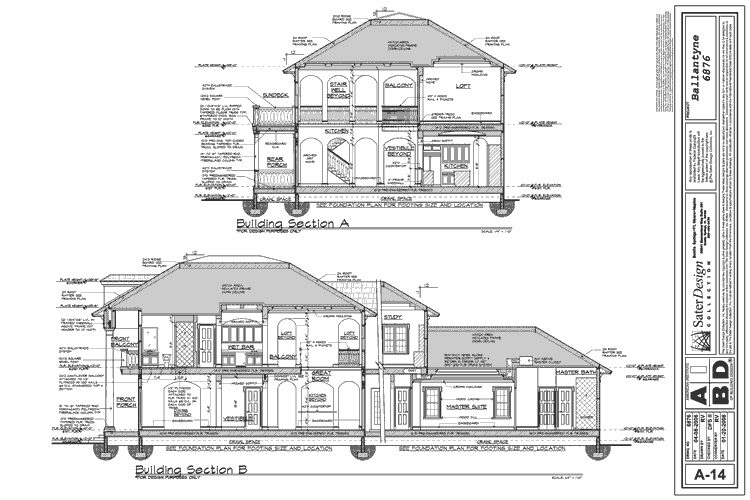
Sections and elevations provide a side profile or “sliced-through” view of major project features, showing what they look like, the elements that make them up, and how to construct them.
Reflected Ceilings Plans (Existing + Proposed)
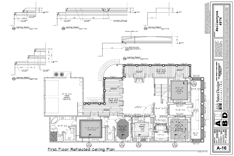
Reflected ceiling plans are the opposite of floor plans. This means that instead of viewing elements that would be on the ground, you get an understanding of what’s happening above. These elements can range from ceiling fans, suspended lighting, air ducts to finishes. Essentially, anything above you that wouldn’t be seen in the plan view.
Details
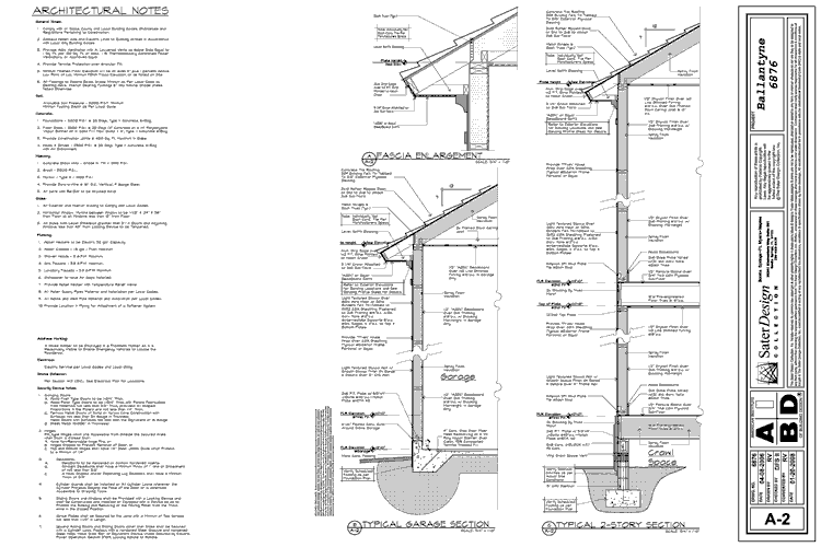
Details are even further detailed blow-ups of specific design elements.
Schedules
Schedules are a complete overview of all elements of architecture required in a construction project. For example, a door schedule can list out every type of door used throughout the project, complete with dimensions, count, and special instructions. This becomes extremely helpful for many reasons. One of the use cases includes estimating the budget and scope of work/logistics.
Did you find this helpful? What is your experience with construction drawings? If you’d like more information, we have these two great resources; “What’s in my set of architectural documents?” and “The Fundamentals of Projecting Plans.” They can be really intimidating for students as construction drawing and knowledge are not always taught in school. We hope we could demystify this very important part of professional work for you! Sharing is caring! We hope to provide you with valuable insights and share them with someone who might find this useful. Make sure to follow our Youtube and Instagram for more content!

I have been browsing online more than 3 hours today, but I never discovered any interesting article like yours. It is pretty price sufficient for me. In my view, if all webmasters and bloggers made good content as you probably did, the web shall be a lot more useful than ever before. “No one has the right to destroy another person’s belief by demanding empirical evidence.” by Ann Landers.